Piuma Evolution
It is the most built among the various models proposed; since many builders adopt more powerful and heavier engines than the original KFM 107 (the most used is the Rotax 447) in the autumn of 2020 it was decided to update the structural calculations for
a weight in flight order of 275 kg (605 lb), indicating on the drawings the changes to be made for those who do not wish to maintain the 250 kg (550 lb) version, which provides for a light engine (about 66 -78 lb).
With further expedients, indicated in the Construction Book, a maximum weight of 300 kg (660 lb) can also be reached.
Basic peculiarities
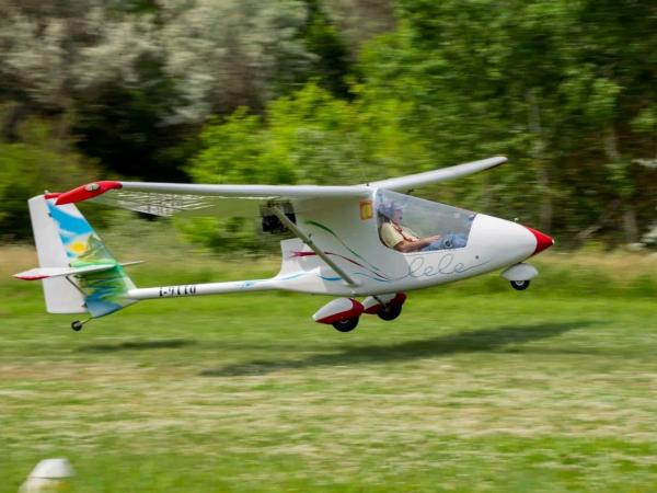
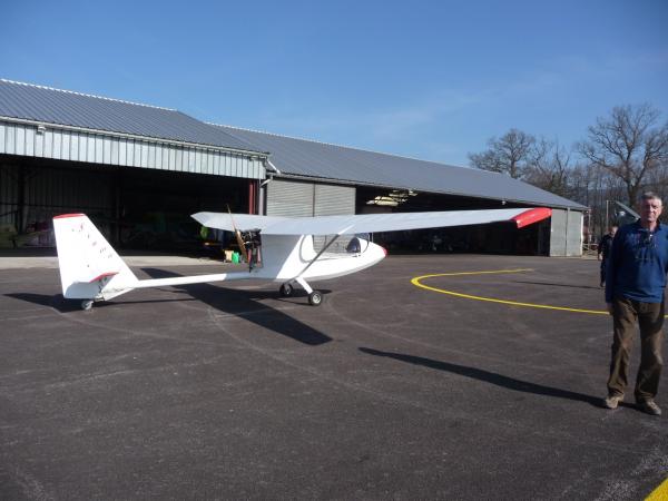
The Piuma Evolution differs from the original Piuma for the following modifications:
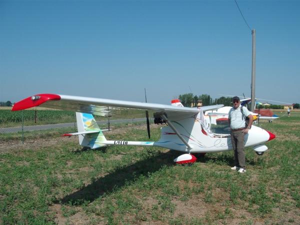
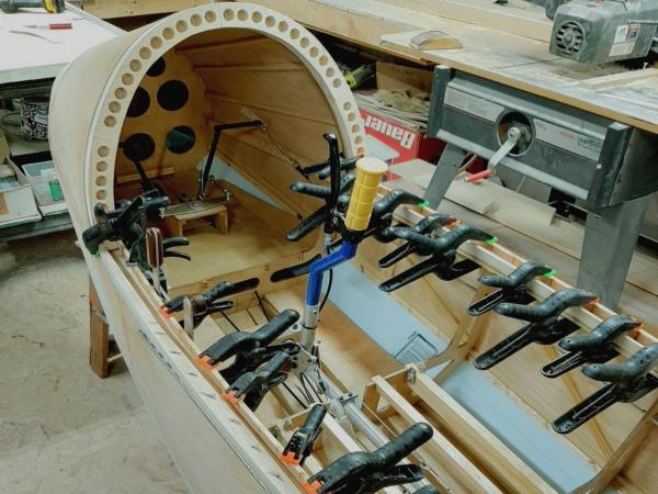
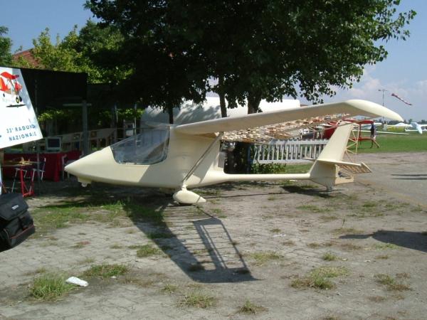
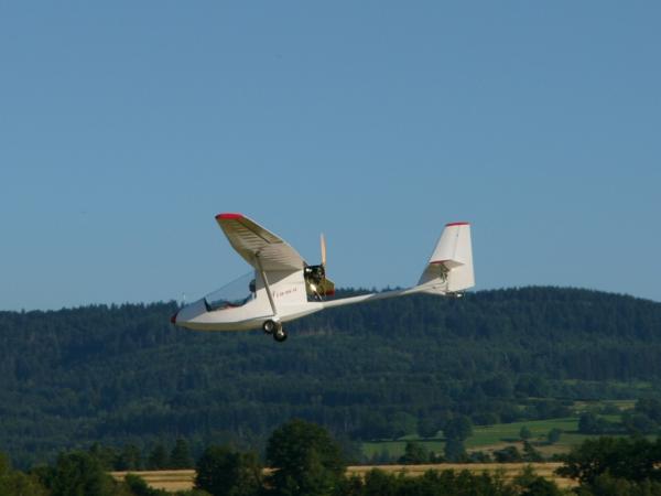
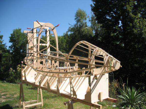
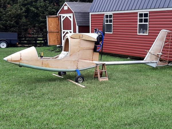
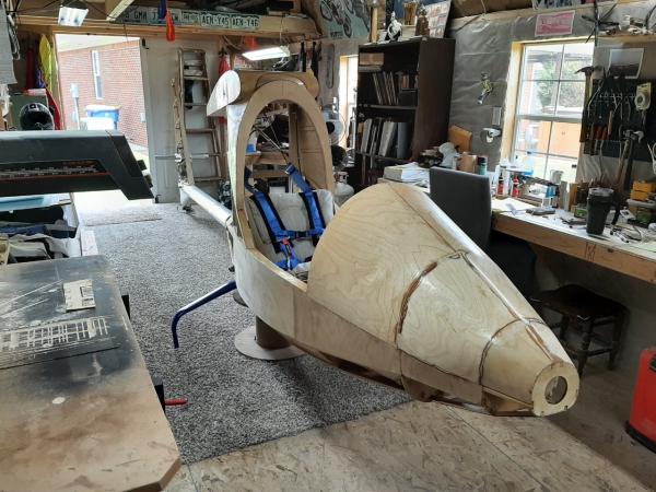
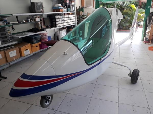
- Fuselage geometry: it is more aerodynamic despite the cockpit being 2 cm wider; the side/bottom area is rounded and the rear tapered to zero under the engine.
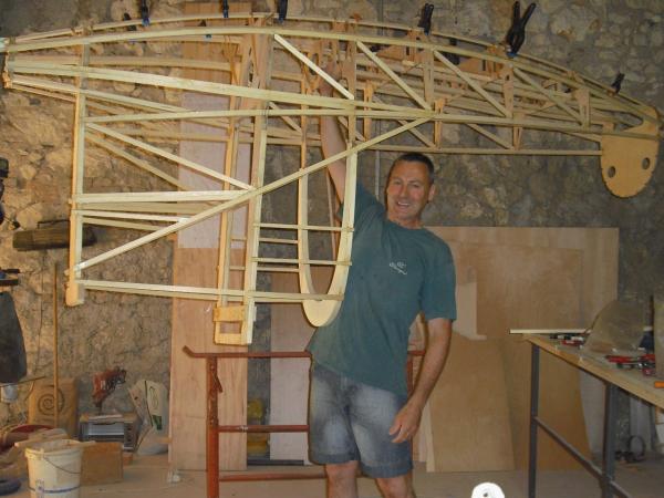
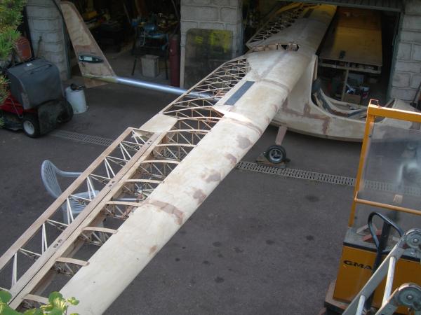
- Wing geometry: the chord at root is 110 cm (43.3 inches) instead of 47,2 inches and the aspect ratio goes from 11.7 to 13. Profile thickness is now 15% instead of 16% and dihedral is now 2° (was 3°). With this new wing the efficiency
has come to exceed the value of 20.
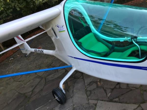
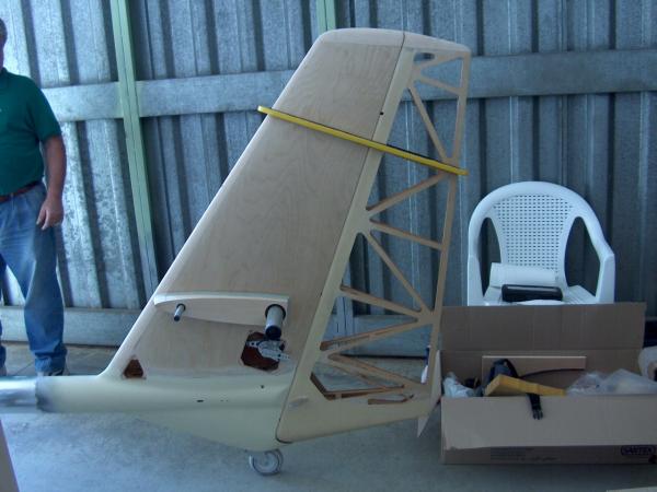
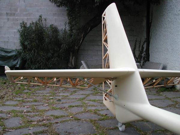
- Geometry of the tail and rudders: they are smaller and with more aspect ratio; the tail is now cantilevered, with two small airfoil struts, eliminating the 8 steel cables.
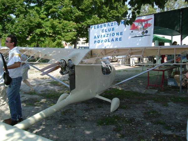
- Wing struts: they are smaller than the previous ones and consist of a drop-shaped aluminum alloy profile; this also improved efficiency.
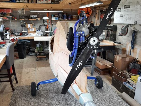
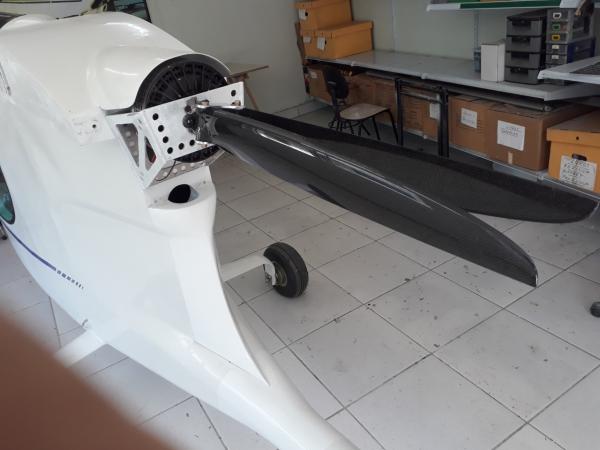
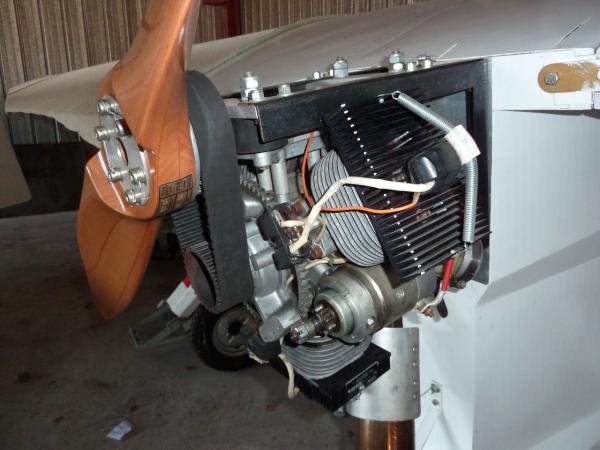
- Engine: in the Original Piuma the heads of the engine KFM 107 were a bit in the shade; in the Piuma Evolution they are in full air flow, greatly improving the cooling. The engine mount designs for the more used Rotax 447 or 503, or
Hirth are also available. With the current small and powerful single cylinders engines it is still possible to build the light version, even if with the improvement of the energy/weight ratio of the lithium batteries it is probable that
the electric motor will become more and more predominant.
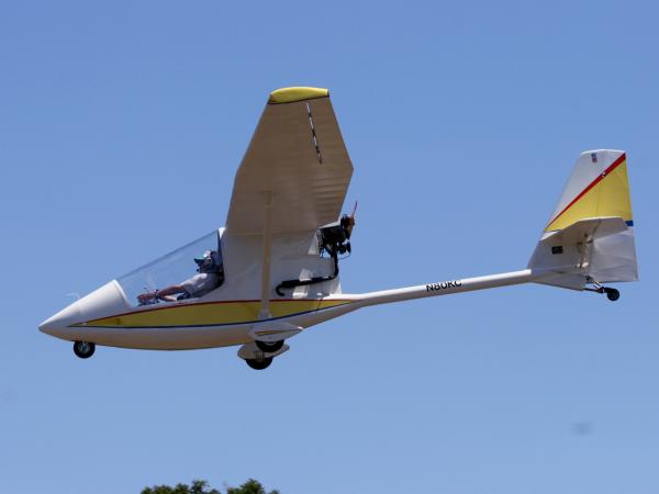
- Nose wheel: it is electrically retractable, but it is also possible to build it fixed, faired and steerable with the indications contained in the project; now almost everyone prefers it in this second version, which is very comfortable
when moving on the ground.
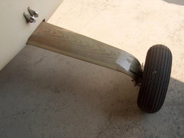
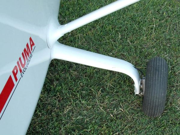
- Main landing gear: the stratified wood landing gear covered with epoxy glass is much more aerodynamic than the steel landing gear of the Original Piuma; some builders have preferred to use the bars in Avional, to simplify and speed
up the construction. The photos are on the DVD.
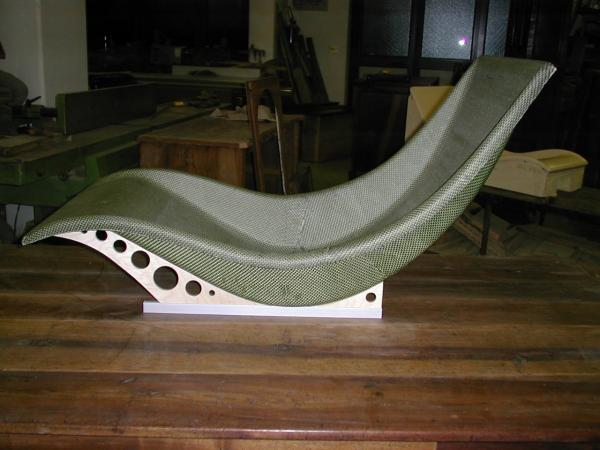
- Seat: it has been shaped for a more relaxed position, like a glider, also comfortable for long journeys: there are detailed drawings and many photos of the construction and it can be used, with the correct sizing, even by persons 6
feet tall (or little more).
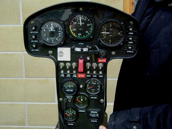
- Instrument panel: it is designed by "glider", it can house the GPS and many instruments and is undoubtedly more beautiful in terms of aesthetics; the dashboard is also illustrated by numerous photos.
- Tail trim on the elevators: it was made electric, with a control instrument on the dashboard; in the plans everything is drawn and explained in detail.
- Air brakes: the controls and the brackets have been improved and designed on a 1 to 1 scale; there are also designs for a slightly more sophisticated “special” version.
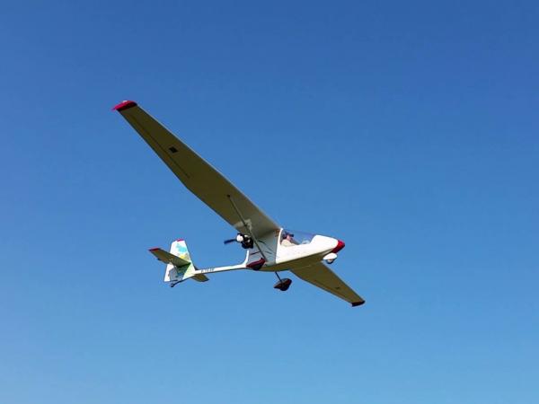
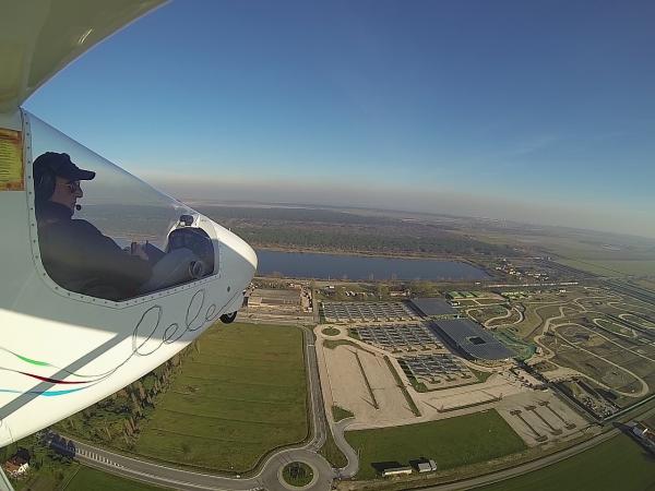
The best L/D is now 20 and the normal cruise is about 75 MPH at 65% power with the Rotax 447, the more used in the construction.
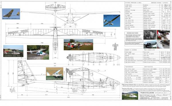
Technical informations – 550 lb version with 66-77 lb engine
Wing span
Total wing area
Aspect ratio
Dihedral
Total tailplane area
Lever arm of tail plane
Length overall
Max height
Empty weight
Max take-off weight
Max wing loading
Recommended load factors (security coeff. 2)
Ultimate load factors
Max level speed
Normal cruising speed
Stalling speed
Never exceed speed
Best glide ratio (at 43 MPH)
Take-off
Landing
Max climb rate at sea level
Min sink rate (at 39 MPH)
Engine |
38.7 ft
114 sq.ft
13
2°
15 sq.ft
10.8 ft
19.7 ft
5.3 ft
350 lb
550 lb
4.8 lb/sq.ft
+3.5 -1.4
+7 -2.8
72 MPH
62 MPH
35 MPH
84 MPH
20
330 ft
330 ft
460 ft/min
165 ft/min
25/30 HP |
Technical informations – 605 lb version
This version is expected to have a 40-50 HP engine weighing approximately 100 lb and an empty weight of 400 lb; the economic cruising speed will be around 75 MPH and a higher rate of climb will be obtainable (from 800 to 1000 ft/min) which also depends
on the type of propeller used.
Construction plans
After the latest update of autumn 2020, they consist of the following:
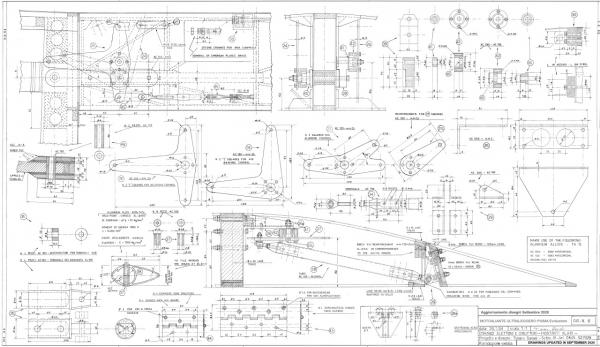
- N. 14 very detailed drawings, with references in Italian and English, in the dimensions of approximately 100 x 60 cm (39’ x 24’); in drawing no. 1 – Triptych – there are now 11 photos, 7 of which are of flying Piuma and 4 of the most
used engines.
- Construction Book and Use Manual updated in autumn 2020 and now 70 pages with 120 photos and 30 explanatory drawings and tables. The first 10 pages are dedicated to materials and equipment, about 30 pages to the various parts to be built
and to assembly; follows the detailed note in 6 pages of all the necessary materials, the calculation of the center of gravity and the instructions for the first flights. There are also the drawings for the construction of more sophisticated
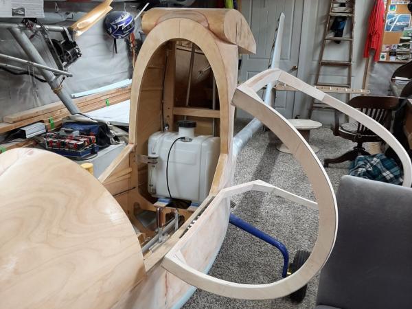
air brakes, the drawings for the tank, for the assembly ladder, for the seat and for the engine mount for Rotax and Hirth engines, as well as the Check-list of pre-flight checks and a hypothesis of weights for the parts to be built. All the
necessary indications to build the 550 lb or the 605 version for particularly tall and heavy pilots have been added.
- Project Book: this too has been expanded and updated in autumn 2020. Now there are 70 pages (with over 100 photos, graphs and tables) containing the structural calculations for a weight in flight order of 605 lb, the calculations of Lift,
Drag, Moment and L/D and in general for the prediction of flight characteristics and various speeds (VNE, VA, Vso, etc).
- Also included is a DVD with 3800 photos of the construction phases of the various Piuma, many photos of the completed and flying Piuma and some in-flight videos, videos which are always visible on Youtube and Facebook (see the links at
the bottom of all pages of the website).
- In the DVD there are also the CAD drawings for laser or water cutting of all the flat metal parts to be made, as well as a note in Excel of all the metal parts to be cut, turned or milled with reference to the
drawing where the part is located.
Other useful information for builders
As an indication, the cost of materials, excluding the engine and instruments, is around 5,000 $ (at 2023 prices); the cost of the engine and instruments is somewhat variable, depending on the choice of the type of new or used engine and on
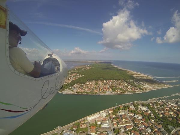
the more or less essential instrumentation; from the photos you have a broad overview of the possibilities offered.
The construction time can be estimated at around 900 hours, having the metal parts made in a workshop.
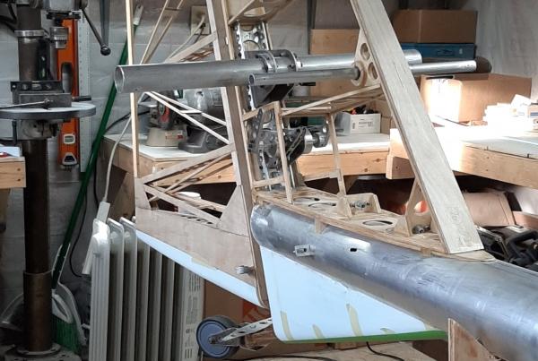
The tail boom is made of 6005-T16 aluminum alloy in the dimensions: external diameter of 127 mm (5”)- thickness 1.5 mm (1/16”)- length 5.2 m (205”); by adapting the fuselage fittings, it is also possible to use slightly different tubes, as long
as their bending strength is not lower than that of the tube above (bending strength values are in the Project book).


